Week 6 - Electronics Production
The Task
Redraw the echo hello-world board, adding (at least) a button and an LED (with current-limiting resistor), Check design rules and make it.
The Execution
Eagle CAD and PCB Design
Some bakground into the use of Eagle CAD software was discussed in Week 4 - Electronics Production >>Eagle Software and PCB design
Open a new shematic and add the following components: Attiny44, capacito 1206, 3x resistor 1206, Button, EFOBM resonator, LEd 1206, FTDI-SMD-HEADER, AVRISPSMD (AVRISP) Add VCC and GND components as show below and connect the sub-circuitsAdd small lengths of wire to each of the terminals on the ATTINY and ConnectorsUse the name function to give correspondong connections the same name and NET.

Check Errors [!] and correct if neccessary
Open Board
Place Components in (+,+) region of view planeUsing a logical orientation - position the components where a 'easy' path can be generated.Use auto-router to generate traces. (this process will rarely work first time so some iterations of moving components and re-doing the autorouter will be neccessary), Manually adding the remaining lines may be easier.Use the DRC option to assign the clearances between the pads and wires , here i used 12mil.Check errors and adjust to correctusuing manual scetch, sketch a wire boundry for the cut-out milling stage.Add a text label

Export image (top layer only) > 600dpi, monochron, window
open image in Gimp (or other) and generate a board image and an outline image

Use Fabmodules to generate a g-code for the board and the pathBoard must be generated using the 1/64 mill end bit, and outline with 1/32 cut out bit
 Here I used 2 offsets to limit the effect on adjacent traces
The tutorial of Anna Kaziunas France (FabLab Providence) was very helpful and greatly appreciated for the design of my board.
Milling
The process of millig the boards on the Sherline 5410 is listed in more detail in the page Milling And Soldering from week 4.
Here a large number of hours was carried out in optimising the cutting process with speed, trace width and layout in the board design, bit type etc. Results are as follows:
 Old v-bit, 2Xoffset, Jog Speed: 162 mm/min, max Vel: 162mm/min
 Old mill end bit, 4X offset, Jog : 162, Max vel: 162
 Old mill end, new design, 12mil traces, 4X offset, jog=200, max vel=200
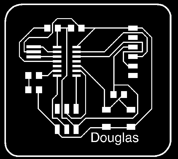
 'Douglas Design, 10mil traces, new Mill End Bit, 2X offset, Jog=93, Max Vel=93
 'hello button', new mill end, 4X offset, jog:162, max vel:162
Suprisingly the best results were achieved with the old mill end bit with 4X offset and high speed. A useable board has not yet been milled, as such the soldering section of this week's task has not been completed...to be continued
Update 11/03/13 : The Issue with milling was finally resolved using a number of changes.
Firstly, the design board was modified on Eagle changing the wire width from 12mil to 20milWhen generating the g-code on Fabmodules, I used 2x offset at an overlap of 0.75
The result required almost zero de-burring.

All components soldered and checked

Tested and currently recieving the orange light, so still requires some trouble-shooting.
Update 15/03/12 Orange light fault was traced back to an error in the design of the board where I missed adding a connection between RST on the 6 pin connector to the the ATTINY. This has been rectified and all working correctly now.